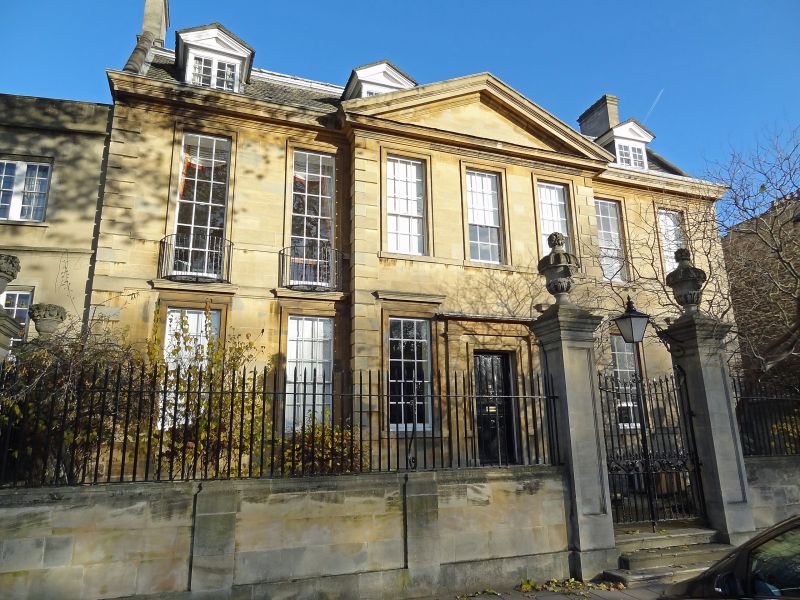
A pediment is simply the expressed gable-end of a pitched roof, finished by means of raked cornices along its inclined edge. It can also be found above windows and doors (exterior and interior).
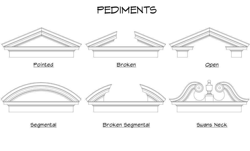
Type of pediment
Determining its geometry
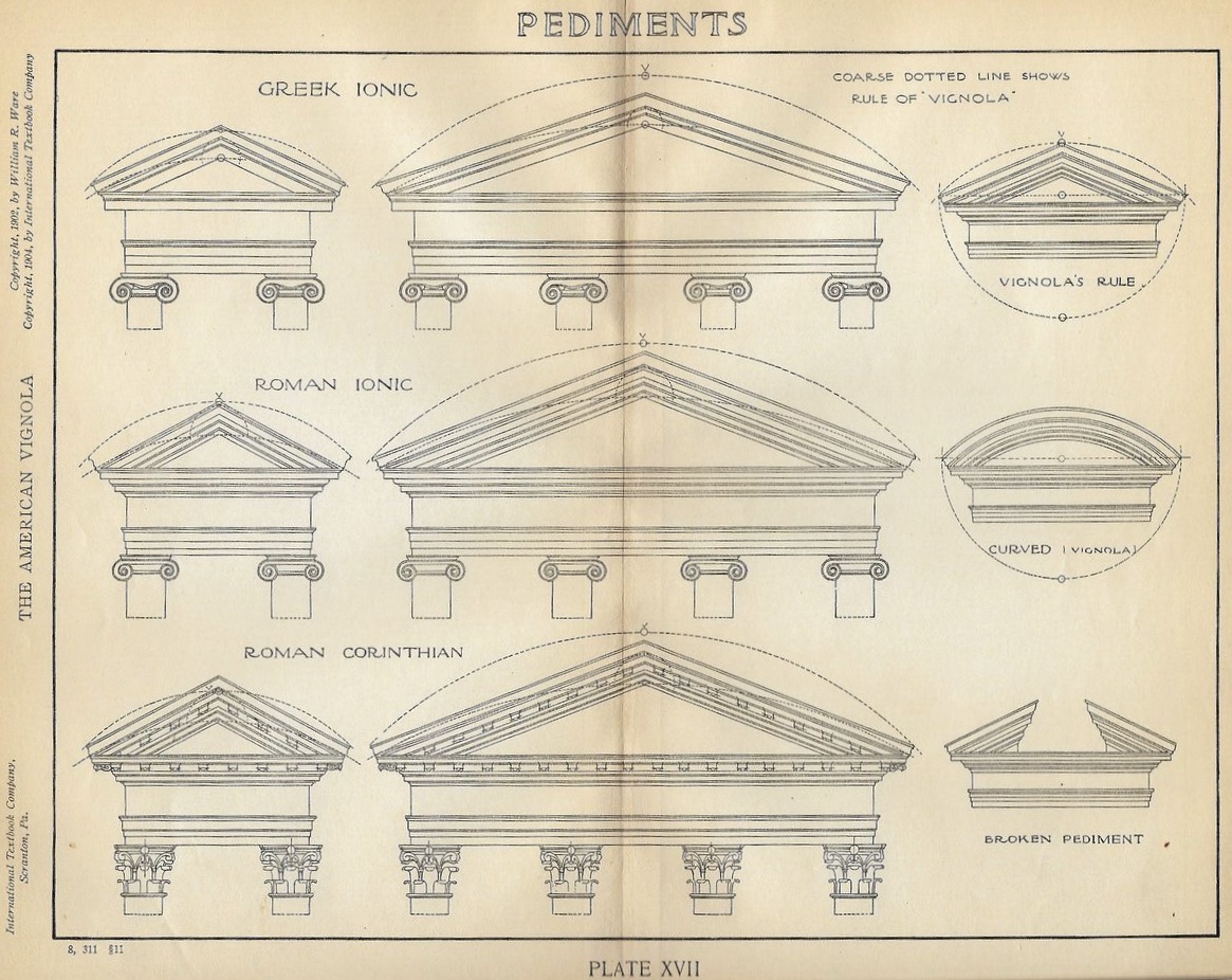
There are a number of way to set out the pitch angle of the cornice, the most common method is using Vignola’s rule.
According to Vignola, the obtuse angle at the top of the Pediment is included within an arc of 90 degrees.
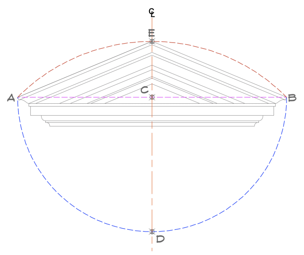
- Draw a line between point A and B (magenta)
- Set centre point C at mid point between A-B
- Use radius of C-A, draw a semi circle with centre point C (blue)
- Set point D where the semi circle intersect with centreline
- Use radius D-A, draw an arc using centre point D and scribe from point A to B (orange)
- Set top of pediment point E where the centreline intersect with arc
Using Vignola’s rule will result with a pitch angle of roughly 22.5°. However Greek / Roman architecture often have a flatter pitch of 17.5° compare to classical architecture.
Although Vignola’s rule can be applied to majority of designs, but it should serve as a guideline and adjust the pitch angle accordingly to suit the rest of the architecture. ie if you have a narrow and tall building, a steeper pitch will suit its proportion more.
Determining cornice return
There are 2 common way the cornice profile returns, each has its own pros and cons. And there are circumstances where you would use one over the other. The choice seems to be one of style: on many simple homes, especially those built for and by tradesman in the late 18th century, square-cut returns were common and more fitting. Whereas, on homes built in the high-Georgian style, plumb-cut (classical) returns were often used.
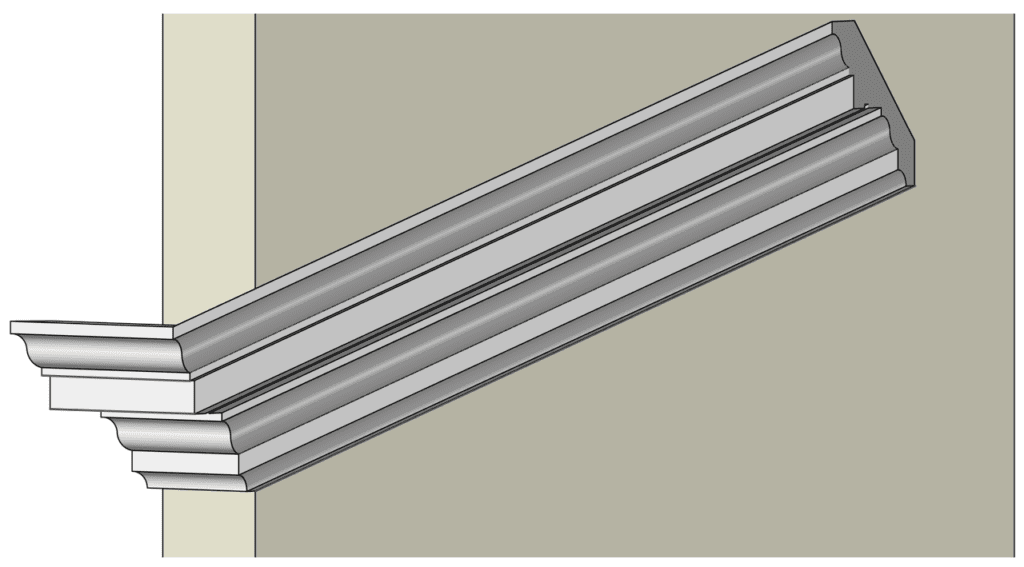
Classical returns
Following the rules of Classical Orders of Architecture, the proportion of the cornice is determined by its classical order (ie, Greek, Doric, Ionic, Tuscan, Corinthian, Composite) and the return profile should be plumb. This result a different profile for the rake than its return profile.
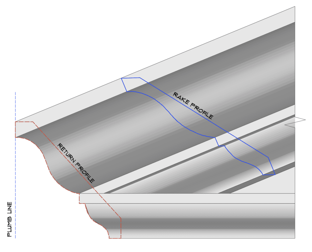
This is particular important if the profile of the pediment returns and join with the cornice that runs along the building.
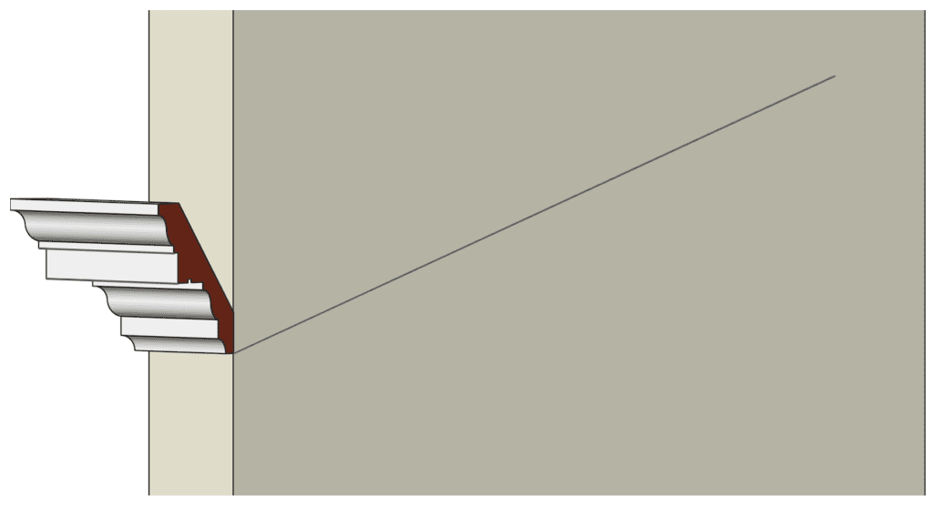
Square Returns (aka Poor Man’s Return)
Similar to the classical return, but instead of using 2 separate profile for the return and rake, it simply use the same profile for both.
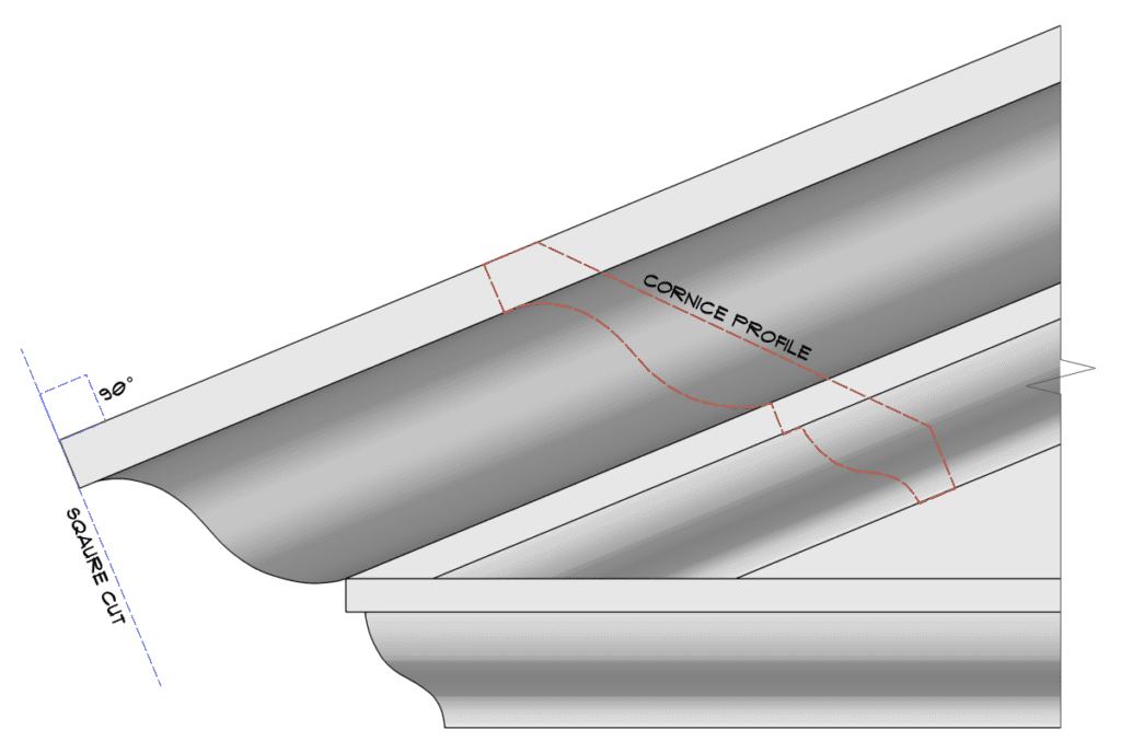
Although this is far simpler to construct as you would simply tilt the profile to the pitch angle (22.5° drawn), however since the return profile is tilted it is impossible to join into cornice that runs along the building as the profile will not match.
Personally I would opt for a square return option if, a)using an off the shelf decorative moulding b)budget / resource constraint; ie no on-site plasterer for bespoke profile moulding or limited time.
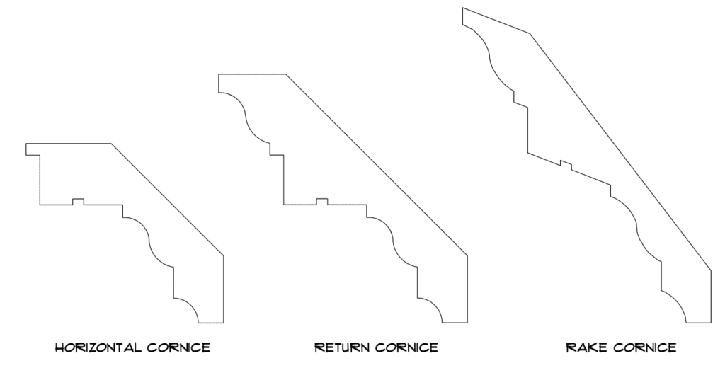
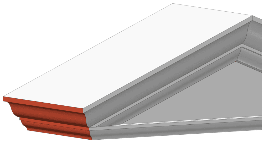
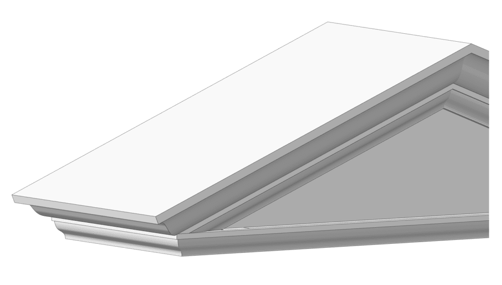
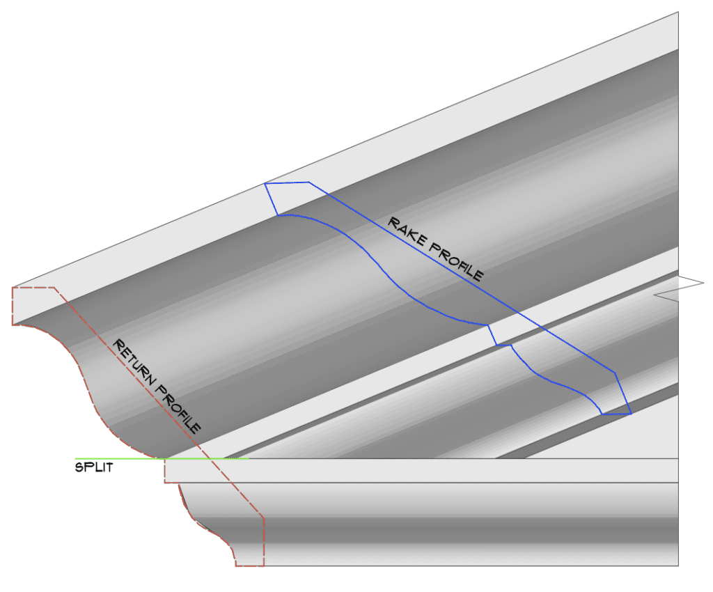
Split Crown Moulding
Regardless of which form of return, one thing that does remain constant. As the mouldings break around the corner, the cornice splits at the crown moulding’s fillet to create a separate raking cornice and horizontal cornice.
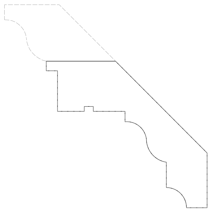
Drawing pediment and profiles
2D CAD or Hand Draughting
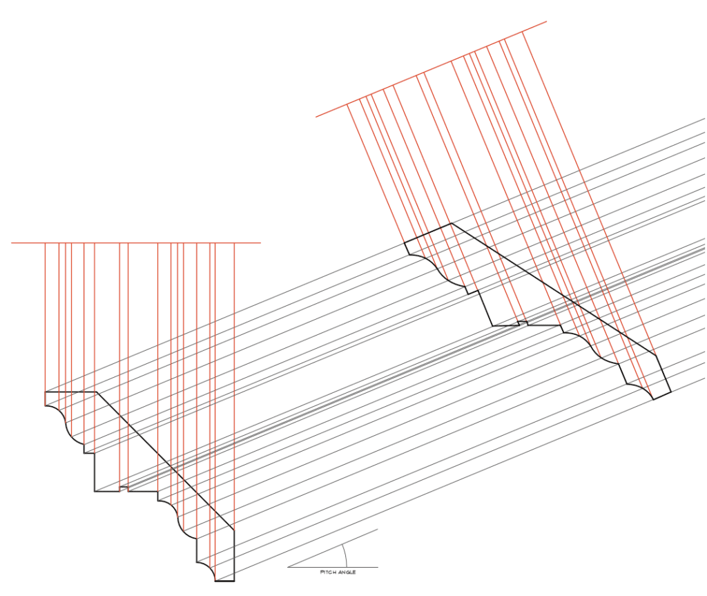
Step 1:
Trace the profile of the moulding.
Then drawn a horizontal line above.
Project a vertical marker line at each transition point on the profile until it meets the horizontal line.
With the curve profile, the more projection lines, the more accurate the rake profile will be.
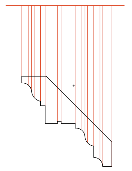
Step 2:
Drawing diagonal guidelines at pitch angle of the pediment (22.5° shown here) at each of the transition point from the profile.
Copy the marker lines (red) and rotate it so that it is parallel to the diagonal guidelines.
Extend the marker lines where necessary, ensure that it meets the corresponding diagonal guidelines.
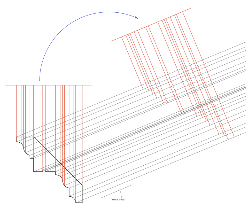
Step 3:
Join the line where the marker lines intersected with the diagonal guidelines, and plot out the shape of the rake profile.
3D Modelling
The same result can be achieved via using 3D models.
Each 3D software’s command might be slightly different, but the principle is the same. I will be showing these steps in Vectorworks. And there are many ways to model it, but I will be showing a method which I feel best describe the logic.
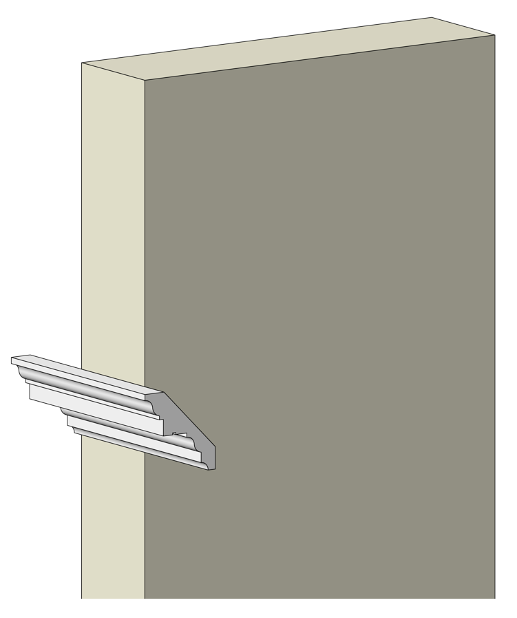
Step 1:
Draw and extrude a rectangular box to serve as a guide to help aligning moulding.
Place the profile on the return side of the box and extrude pass the corner as shown.
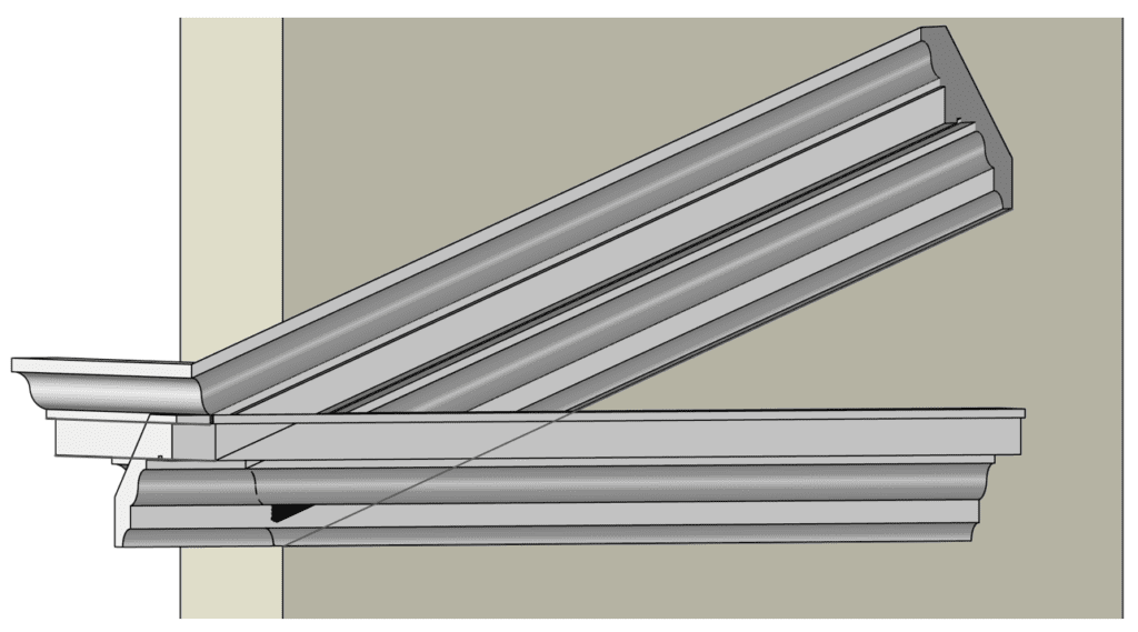
Step 2:
Trim off the extruded moulding at the corner of the box, 45°.
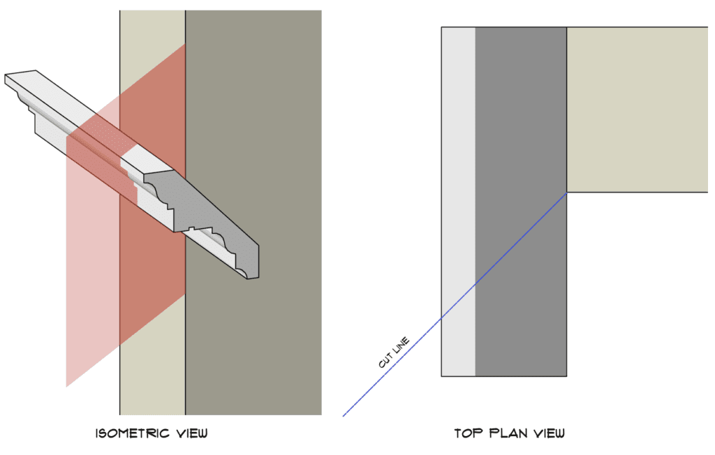
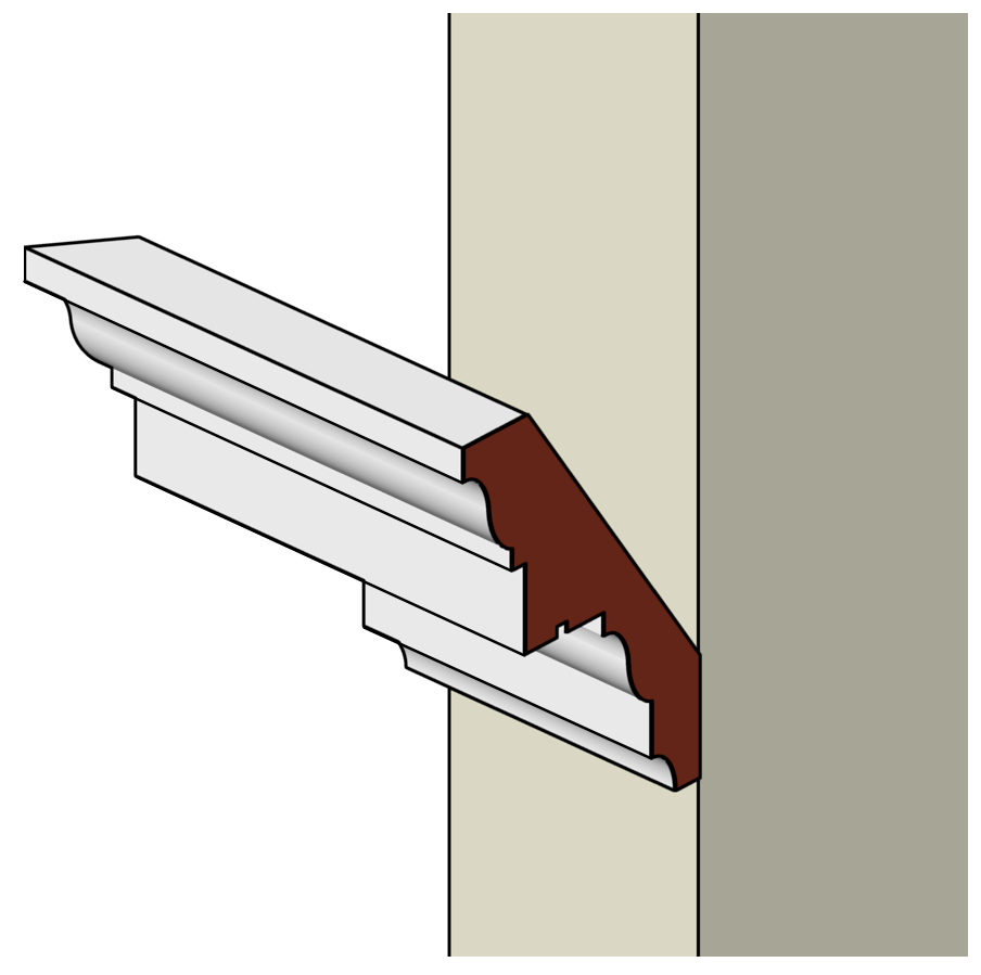
Step 3:
Remove the excess part of the moulding.
Extract the mitre surface of the moulding, highlighted in red.
(Vectorworks – Extract, then Convert Nurbs Surface to 3D Polygon; Rhino – ExtractSrf; Sketchup – Copy and Paste in Place)
Step 4:
Draw a line on the front face of the box, set at the pitch angle (22.5° shown here). Ideally longer than the length of the pediment’s raking cornice.
Step 5:
Extrude the extract surface from Step 3 along the path drawn on Step 4.
Step 6:
To complete the pediment with its horizontal cornice, as mention before, the moulding split at the crown moulding.
Take the profile used for the return moulding, trim off the split crown profile portion.
Place perpendicularly and on the front face of the box. (Make sure the bottom edge lines up horizontally to the return moulding)
The extrude pass the corner of the box.
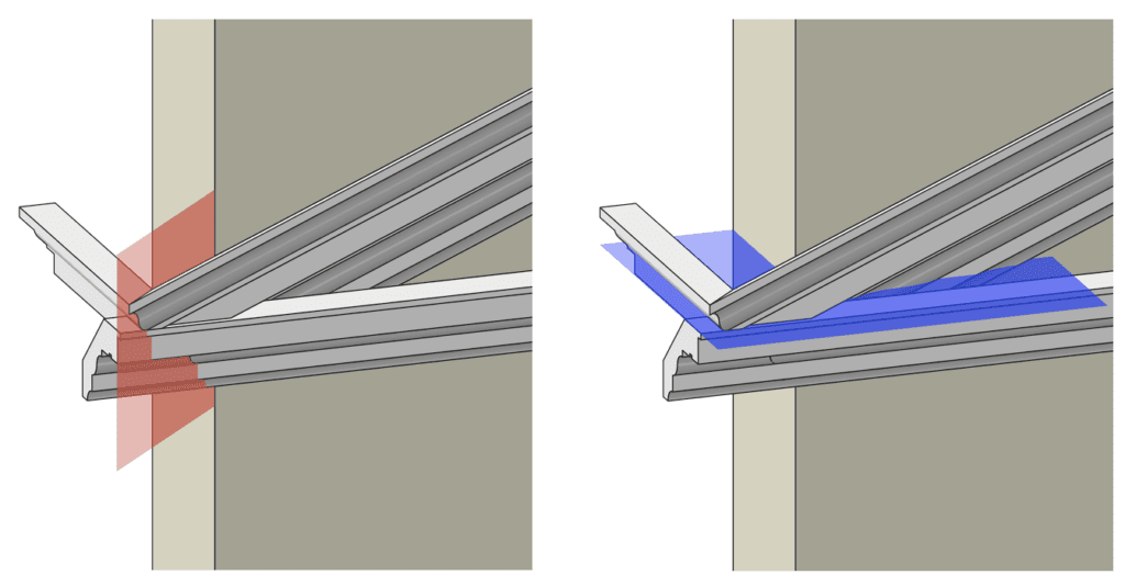
Step 7:
In order for the horizontal cornice to join with the return moulding, we will need a 45° trim at the corner – show in red (described in step 2), and also trim off the rake cornice horizontally where it meets the horizontal cornice – show in blue.
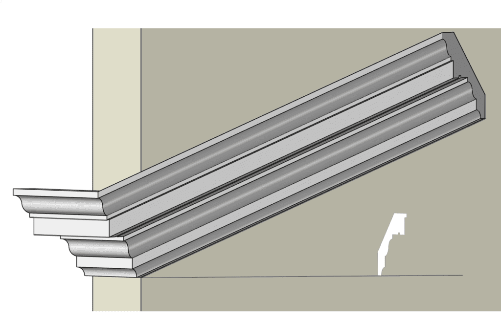
Step 8:
To extract the rake cornice profile, simply take a perpendicular cut to the rake cornice and extract the profile to be place on the drawing and hand off to construction.
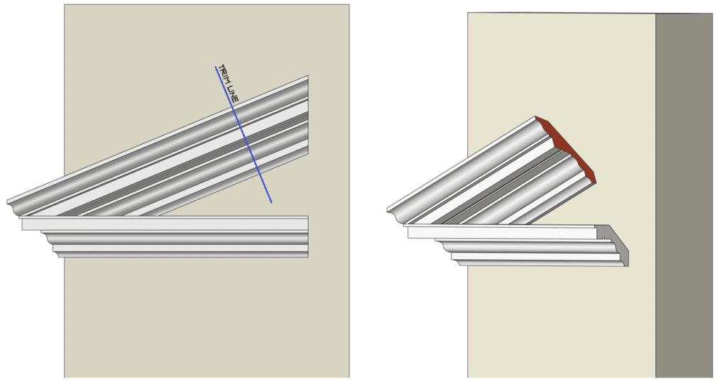
There you have it, all 3 profiles for construction.